This report provides a comprehensive analysis of the Nokia Networks 5G AirScale Digital Baseband Unit (BBU). The configuration of the 5G AirScale is:
AMIA Subrack
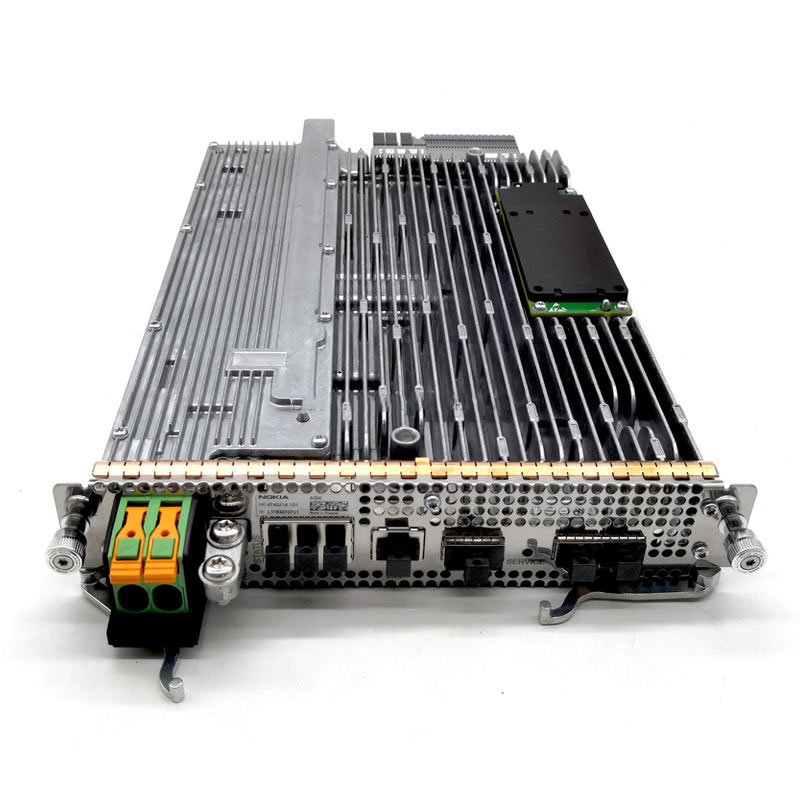
ASIK Common Plug In Unit
ABIL Capacity Plug In Unit
Features
System Functional Description
System Level Block Diagrams
High Level Mechanical Analysis
Heat Sink
High Level PCB Analysis
Component Diagrams
Semiconductor/component locations on PCB
High Level Bill of Materials
Semiconductor ICs (ASICs, FPGAs, memory, logic, power, etc.)
Passive/other components (Transformers, Power inductors, Power capacitors, power/datacom/optical connectors)
Complete Part Number/Marking
Component Manufacturer Identification
Function Component Description
Package Type
Excludes analysis of low power passive chip resistors, capacitors, and inductors
CHAPTER 1: AMIA SUBRACK
AMIA Guiderails
ASIx Blind Slot Frame
ABIx Blind Slot Frame
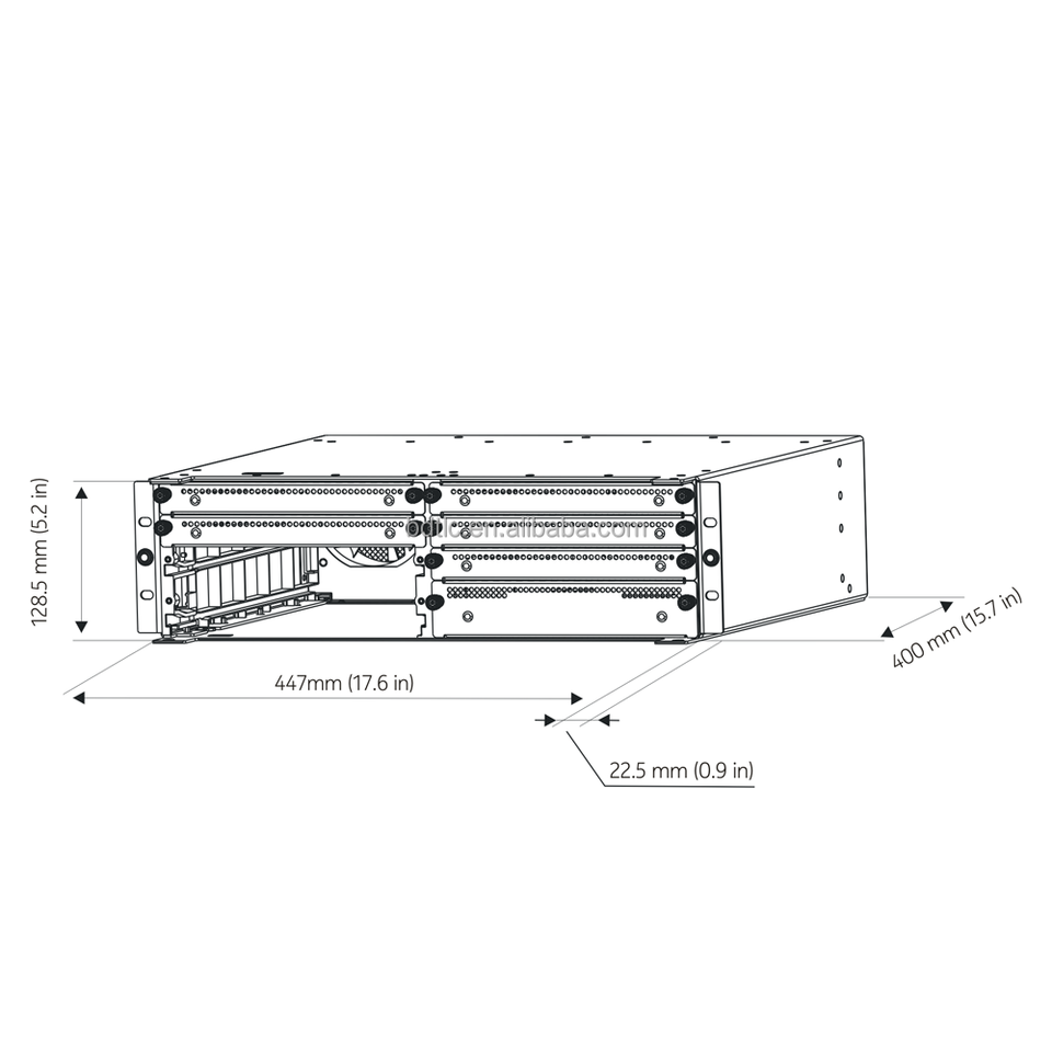
AMIA Chassis: External Views and Dimensions
AMIA Chassis: Backplane and Fan Units
AMIA Backplane

CHAPTER 2: ASIK PLUG IN UNIT
ASIK Front Panel & Handles
Power Supply Unit (PSU)
PSU Top Cover Heatsink
PSU Bottom FCTL Heatsink
PSU Printed Circuit Board Analysis
PSU Input DC Voltage Connector Assembly
PSU DC Busbar Assembly
ASIK FCTL PCB
eUSB Flash Card
OCXO Module
ASIK FCTL Bottom Cover

CHAPTER 3: ABIL
ABIL Front Panel
ABIL ASPA Heatsink
ABIL ASPA Cover
ABIL ASPA PCB

AirScale System Module
This baseband module is designed to be agile and enable long-term network evolution. The in-node modularity of the AirScale System Module is key to lean entry and decoupled scalability of the compute power for radio access network layers 1, 2, and 3 and integrated transport functionality – essential for the rapidly changing traffic requirements of new use cases and deployment scenarios of the 5G era.
The AirScale System Module simplifies 2G, 3G, 4G and 5G Single RAN deployments, streamlines multi-band sites and powers multi-site baseband hotels.